Soundcard Interface
Making accurate measurements needs good equipment, but good equipment can be expensive. The computer itself is a potential versatile instrument, via the soundcard, but some modifications are a good idea to protect it and to try to keep out the noise generated by the computer.
There are three main sections to this interface: A differential amplifier to isolate the circuit under test from the soundcard; A bandpass filter to assist the soundcard in producing a pure tone for distortion measurements; A notch filter to increase the resolution of distortion measurements. For simplicity, the bandpass and notch filters are tuned only to 1kHz.
Differential amplifier
To help keep noise pickup to a minimum, a differential amplifier sits between the circuit under test and the soundcard input. It also presents a high impedance to minimize loading of the circuit under test.
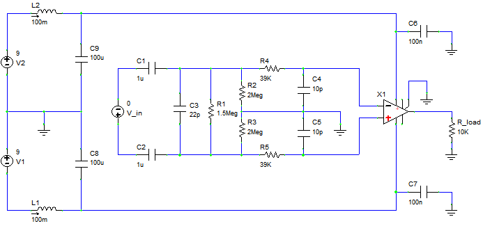
It is powered by two 9V PP3 batteries which are LC filtered to keep noise down. The inductors need to have significant internal resistance, or additional series resistors added to damp the LC filter's resonance. The particular inductors I used have about 60Ω resistance, which is sufficient.
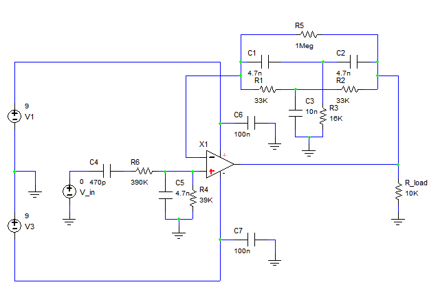
X1 is an instrumentation amplifier (IA). Instrumentation amps have differential inputs, which is what is needed here, and this particular one (INA128PA) also has input overvoltage protection up to ±40V, which in conjunction with the DC blocking capacitors C1 and C2 make it pretty safe for measuring anything up to that voltage. Even higher voltages could be measured by using x10 or x100 oscilloscope probes, but I wouldn't recommend that for safety reasons.
The input impedance is set at approximately 1MΩ||22pF (capacitance will actually be a bit higher than that due to parasitic capacitance of wires etc), which suits standard oscilloscope probes. R2 and R3 provide a path for the IA's input bias current. R4/5 and C4/5 filter out RF.
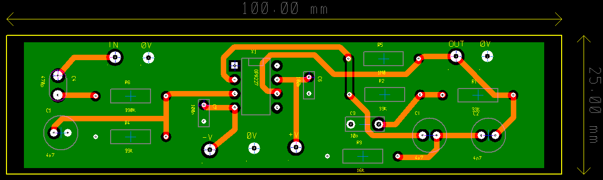
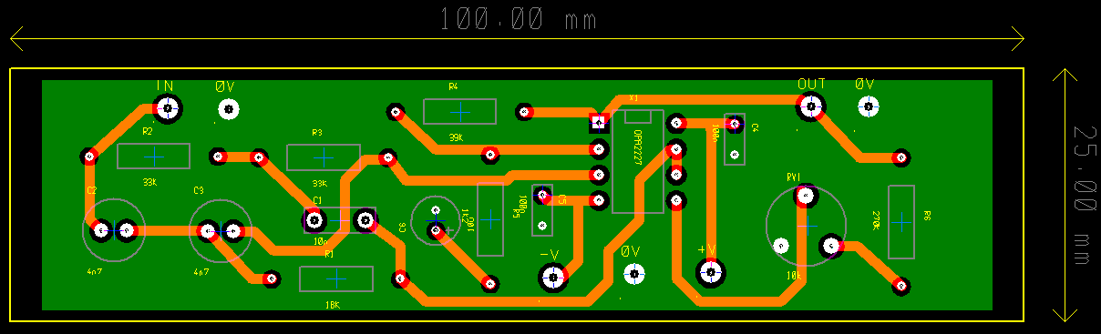
Here's the PCB layout (click to enlarge):
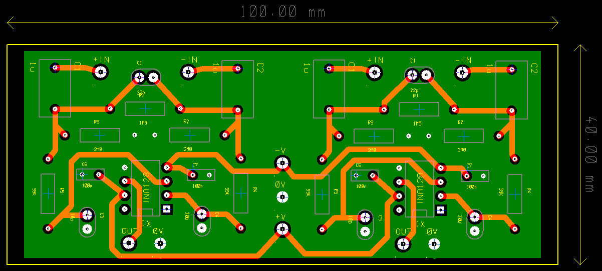
It uses a ground plane to minimize noise.
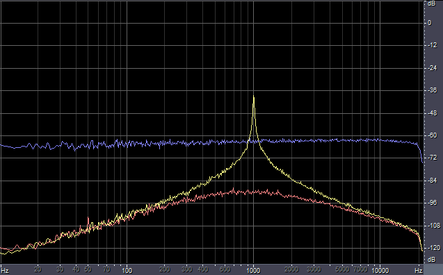
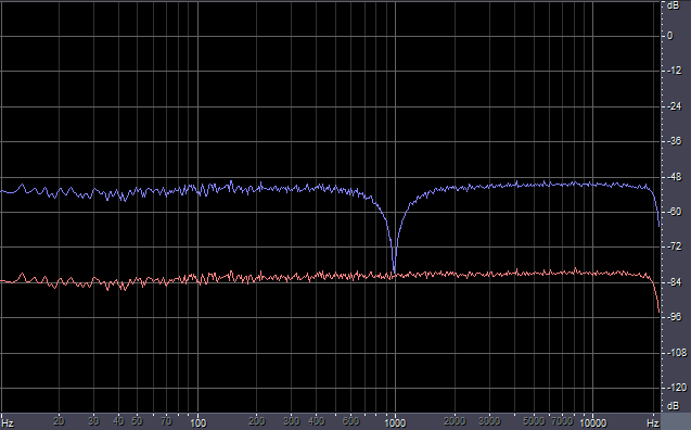
Following is the noise floor:
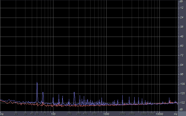
The red line is the noise of the soundcard itself (SW1000XG) with the input grounded. It's better than -132dB mostly, with just a couple of high-frequency peaks which are presumably noise picked up from inside the PC's case. The blue line is with the differential amp connected up and with a scope probe attached and shorted. Noise isn't much higher than that of the soundcard, but there are many new peaks at mains frequency + harmonics and a few higher frequency peaks picked up from somewhere, despite all the circuitry and cables being pretty well shielded. The amount of extra nose picked up varies a lot, being lower at night.
Bandpass filter
To perform distortion measurements requires a low-distortion sine wave source. A soundcard can provide a sine wave, but it may not be very clean. A bandpass filter can be used to filter out all the unwanted frequencies, leaving a nice clean fundamental. Initially I experimented with a simple RLC resonant filter, but the required inductor value was so large that it had to have a high-permeability core, which added a very large amount of distortion. After testing many other filtering techniques, the most effective overall turned out to be a twin-T feedback op-amp circuit combined with a passive RC bandpass:
C4, R5, C5 and R4 form a very low Q passive bandpass filter to remove DC and very low frequencies and keep very high frequency rubbish away from the active circuitry. They also attenuate the input signal to compensate for the high overall gain of the circuit. This is followed by an op-amp with feedback applied via a twin-T notch filter. The sharpness of the resulting peak in the frequency response depends on the tuning of the twin-T network: If it's tuned too accurately then the circuit will oscillate; if it's tuned badly then it won't attenuate unwanted frequencies enough. The given values work pretty well for me.
It's important to use a quiet, low-distortion op-amp here, since the distortion generated by this circuit will limit the resolution of distortion measurements possible with it. I chose an OPA227, which has both very low noise and distortion.
Here's the PCB layout (click to enlarge):
Finally here's the frequency response of the finished circuit:
The blue line is the input signal, the red line is the frequency response of the passive RC network, the yellow line is the overall frequency response. Gain at 1kHz is about 24dB, 2kHz is attenuated by better than 40dB relative to that. That's enough to effectively remove all the noise and distortion from the input, leaving only that generated by the filter itself.
Notch filter
At maximum level, my soundcard input adds -96dB 2nd harmonic distortion. This limits the minimum distortion I can measure directly. To overcome this limitation, a notch filter can be used to reduce the amplitude of the fundamental without affecting the harmonics, effectively magnifying the distortion to bring it well above that generated by the soundcard. Once more, a twin-T network comes in handy, this time at the input to an op-amp. A second op-amp is used to increase the Q of the circuit so that the attenuation at 2kHz is negligible while maintaining good attenuation at 1kHz.
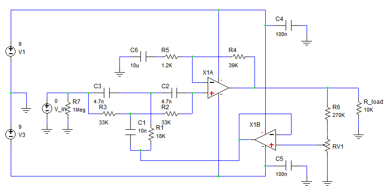
RV1 (10kΩ) varies the Q. If it is tuned too low then harmonics will be attenuated, if it's too high then the circuit goes into oscillation. Like the bandpass filter, the twin-T network is detuned slightly to prevent oscillation. Detuning also slightly widens the notch, making measurements less sensitive to slight deviations in the test frequency from 1kHz.
A low-noise, low-distortion op-amp is good to use here, so I chose an OPA2227 (dual OPA227).
In order to maximize the resolution of the measurements possible with this circuit, it must be connected directly to the circuit under test, not via the differential amplifier. This means it lacks protection from unfortunate accidents. It is fairly robust against quite high input levels, but too much and the op-amp will be destroyed.
Here's the PCB layout (click to enlarge):
This is the frequency response of the notch filter:
The red line is the input, blue is the output. This is about the best Q I can get without either instability or a notch so narrow that even deviations of a fraction of a Hz from the tuning frequency are attenuated far less than exactly the right frequency. Attenuation at 1kHz is 30dB, with attenuation at 2kHz low enough to ignore. There is also 30dB of overall gain.
Here are some actual distortion measurements made with the bandpass and notch filters. The levels have been adjusted so that the magnitude of harmonics can be read directly off the scale.
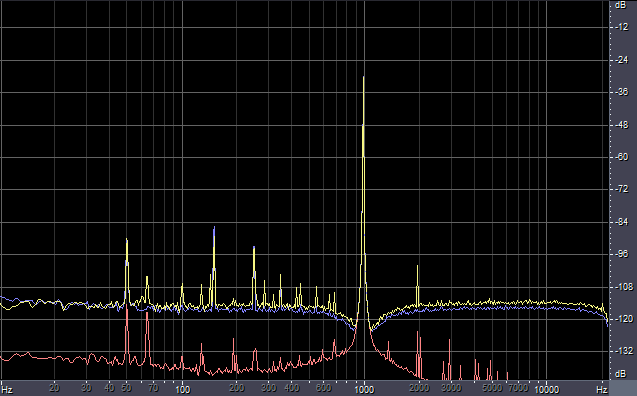
The red line is with the bandpass fed directly into the notch filter, which represents the absolute minimum I can measure.
The blue line is an OPA134 - an op-amp with exemplary performance. It's in a non-inverting gain of 100 configuration, unloaded, 2V p-p output. There are no harmonics visible above the noise floor at all.
The yellow line is an OPA604, which is a very poor op-amp (despite the good specs in the datasheet). In the same configuration as the OPA134 it shows 2nd harmonic at only -100dB.
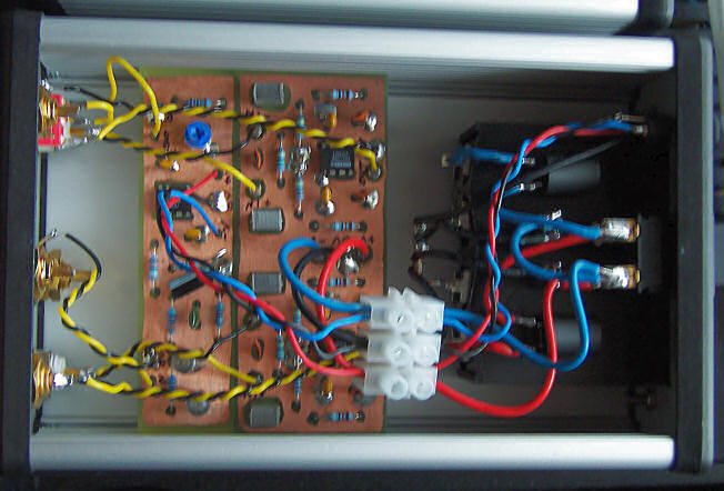
Finished article
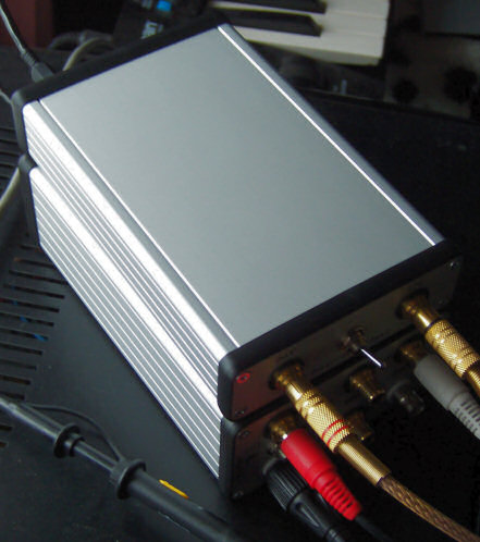
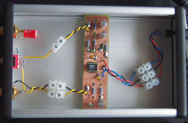
Below can be seen the main enclosure containing the batteries and associated LC filter on the right, the differential amplifier in the centre, the notch filter on the thinner PCB to the left of that and the various connectors on the far right. The notch filter has its own input connector to reduce the risk of it being connected to unsafe voltages.
The other enclosure contains the bandpass filter. It's separated from everything else to prevent noise coming in from coupling straight to the output. The filter can be switched in for distortion measurements, out for everything else. Note the capacitor and resistor in series with the output. These block DC (in case the output is accidentally connected to something it shouldn't be) and limit short-circuit current respectively.
The final photo is of the whole lot set up. Having used it a bit now, it definitely is a very useful bit of kit. It is capable of making quite sensitive distortion measurements that might otherwise need an expensive distortion analyzer, as well as a plethora of other types of measurement.