USB Blinkenlights
Flashing lights. Lots of flashing lights. It's how you can tell that a piece of equipment is doing something important. My file server definitely does all sorts of very important things, so it needs a particularly impressive array of lights. The lights actually are useful because the file server has no monitor, so the lights allow its status to be seen without having to log in over the network. They also provide an opportunity for me to experiment with making a USB peripheral, which I haven't done before.
There are three parts to the project: The circuitry, the firmware and the software.
Circuitry
This is further split into three parts: The USB interface, the motherboard and the daughter boards (hereafter called "modules"). The USB interface is simply an off-the-shelf part purchased from Devantech. It's a tiny little thing based on the FTDI FT232R USB UART and a PIC microcontroller. It translates data sent over USB to I2C, which is an ideal bus for communicating with multiple modules due to its electrical simplicity (only two wires).
The motherboard has no function other than to connect the I2C bus and power to all the modules' connectors.
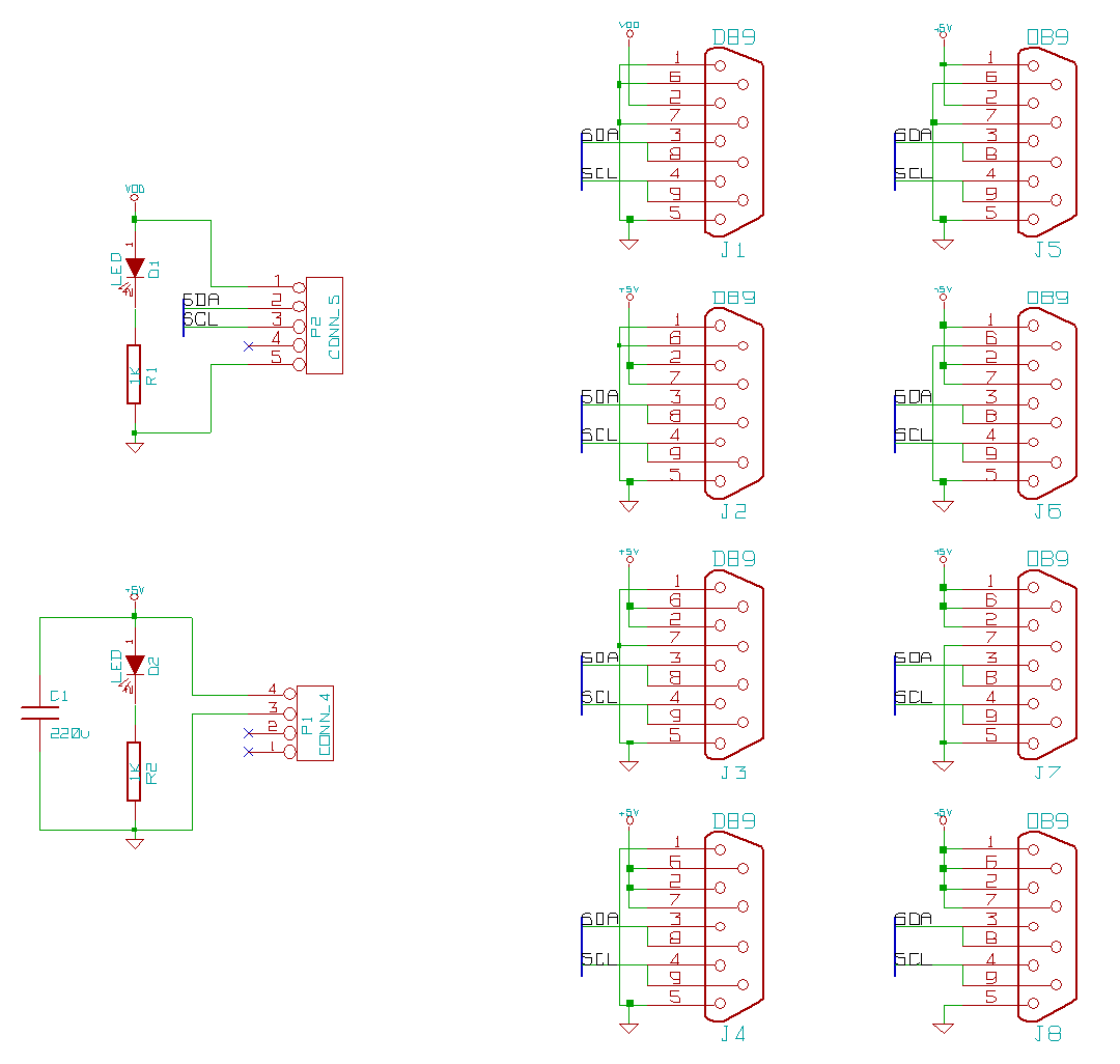
The USB-to-I2C module can only supply 70mA, which is only enough for about one module, so the others are powered from a Molex connector.
The modules are also very simple. They are based around PIC16F690 microcontrollers, chosen because they have I2C capability built in, and enough digital outputs to control the seventeen LEDs I planned on.
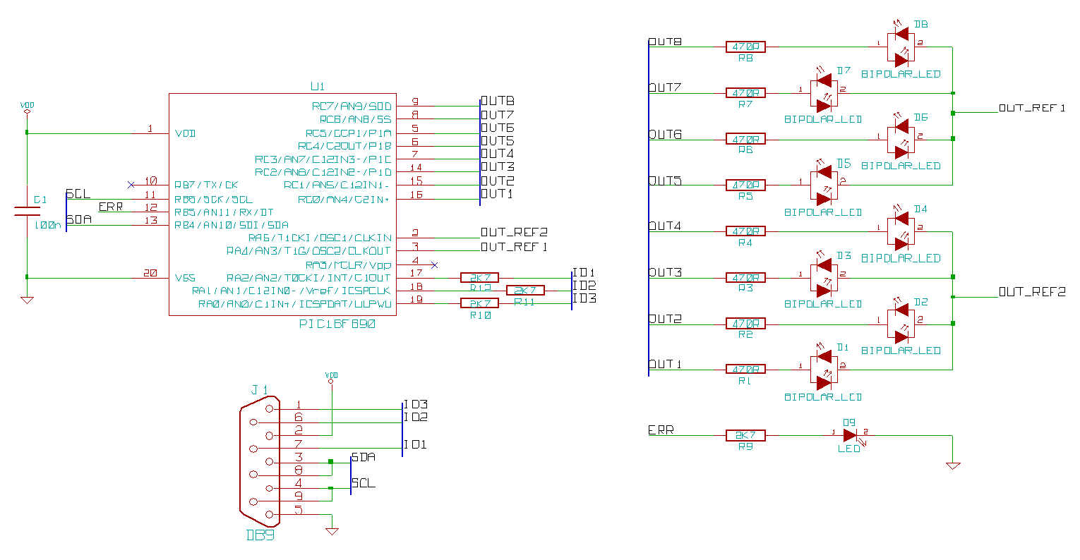
The seventeen LEDs are actually eight bi-colour green/orange LEDs and one red LED (used as an error indicator). The microcontroller does not have enough outputs to control that many individually, so a little bit of trickery is needed: The bi-colour LEDs have their LEDs connected in antiparallel, so if pin one is high and pin two is low then one colour lights, if it's the other way around then the other colour lights. By switching polarity very fast, it will appear as though both are on simultaneously. To achieve this, all the pin twos of the LEDs are connected together (actually they are split into two groups because otherwise too much current would be drawn from a single one of the PIC's outputs) and the pin ones are connected to individual outputs. The common pins are alternated between high and low, allowing both colours of LED to be lit alternately. The red LED is just connected normally to its own output.
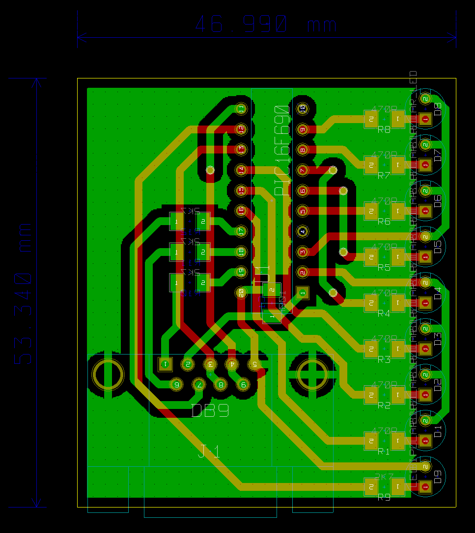
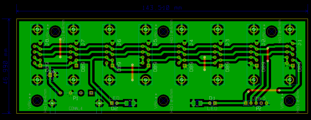
A double-sided PCB is necessary for this, although it was possible to make one side almost entirely a ground plane, which should help keep nasty transients from switching the LED current at high speed from escaping.
Firmware
Communication between the PC and the modules conforms to a simple protocol, and it's the firmware's job to implement the module's side of it. The first thing it does is read the values of the spare pins on the DB9 connector and uses them to calculate its I2C addresses (each physical module is really two logical modules with two addresses, one for each colour of LED). Data can be sent over the bus to an address as a single unsigned byte. The module displays the value on the LEDs as a bar graph, with 0 being no LEDs lit and 255 being all lit.
Data should be sent at a fixed rate, although the rate can be anything from 1 byte per two seconds to as fast as the I2C bus is capable of. The module measures the time between bytes and linearly interpolates the value displayed on the graph between the last and current values, so even though only one value per second might be received, the display appears to move smoothly during the time between bytes. If more than two seconds elapses without any data being received, the graph turns off and the red error LED turns on.
The final function of the firmware is to respond to an I2C read operation and send back something back to the PC, e.g. a description of what the module is.
You can view the code if you want. It's written in assembly using Microchip's own MPLAB IDE.
Software
The software is capable of measuring various things, like CPU use or remaining disc space. It translates those metrics into a single byte and sends them over USB.
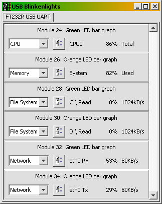
Each I2C address is listed as an individual module, two of which together make up a physical module board (one green and one orange). The module numbers are the raw I2C addresses, which is why they don't start at 0 or 1. You can see that there is a tab bar at the top. This is because the software technically supports multiple USB devices, although since I've only built one I can't test that. Up to 16 modules (8 physical boards) can be attached to the motherboard, but the motherboard could be expanded by attaching something in place of a module that connects to even more modules, and the software can theoretically use the whole 7-bit I2C address space, should I ever need that many.
I wrote the software in Java, not just because it's my current primary language, but also because I wasn't sure what OS the fileserver would run and Java makes it easy to use any. I used the Sigar API for gathering the system information, and there is very handily a Java library for the FTDI chip.
I haven't bothered to put the source code for the software on my site, but if anyone really wants it I'll send it to you.
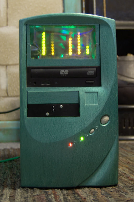
Complete System
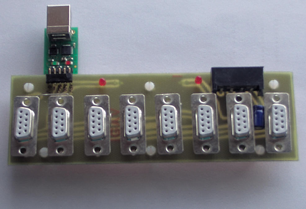
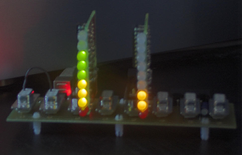
The whole system works perfectly. I made three modules for it, but I will make more eventually. Anything could be attached to the system as long as it obeys the protocol, not just LED bar graphs. Developing for USB turned out to be extraordinarily easy thanks to the FTDI chip with its ready-made drivers.
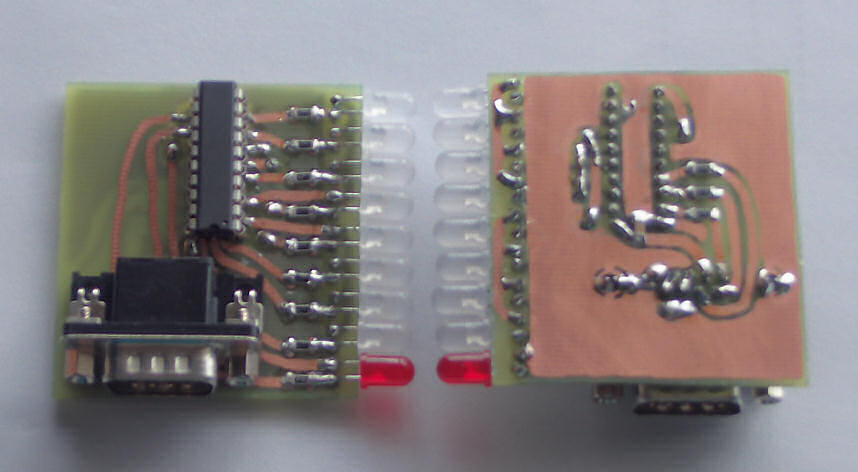
The bit of wire on the left in the above photo I put in temporarily to bridge power from the USB side to the side that should be powered from the Molex connector, since I didn't have such a connector handy outside a PC case.
The camera has done a poor job of accurately capturing the colours, but in real life it's possible to see the two colours of LED superimposed on each other so that both graphs are distinguishable.
I encased the circuitry in bits from an old CD-ROM drive so that it could be fitted into a drive bay (it takes up two drive bays actually). It's connected to the internal USB connector on the USB PCI card in the server (I knew those internal connectors were good for something!).