Desk Fan
With unpleasantly hot weather becoming increasingly common, cooling has gone up in my priorities, and fans are a cheap and effective way of cooling people down. We have quite a few fans throughout the house, and it's proven to be hard to predict their quality before purchasing them. Some are excellent, but some are noisy, usually due to being poorly balanced. We could replace the bad ones, or try to balance them, or I could take the opportunity to build something new. No prizes for guessing which route I chose.
Fan Parts
Noticing the popularity of drones, I wondered if among the plethora of spare parts for them I could find something suitable for use as a fan. There are plenty of propellers available in a wide range of sizes, so it wasn't hard to find something potentially useful. They generally have only two or three thin blades rather than the larger number of wider blades that would be more suitable for moving large volumes of air at low speed, but I thought they would probably work ok anyway.
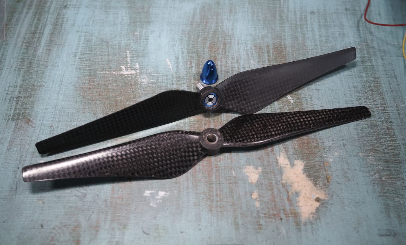
I acquired two nominally 9.5" propellers and attached them both together to form a single four-blade propeller. More blades means more air moved at a given speed, which should result in less noise, or at least less objectionable noise. They are attached together and to the motor with an adapter (the blue and silver parts in the photo) that's very much like the collet of a drill, clamping around the shaft of the motor. The adapter was only long enough to fit through one propeller, so I had to drill a large hole in the other and glue part of the adapter inside.
I wanted to use a drone motor too, but they are all designed to run at extremely high speeds (>10k rpm), whereas a fan should run relatively slowly so as not to be too loud, or blow away the person to be cooled. I still wanted to use a brushless DC motor though, rather than an AC motor like normal desk fans use, because brushless DC motors are small and efficient, and I can use a commonly available DC wall-wart and not have to deal with mains voltages.
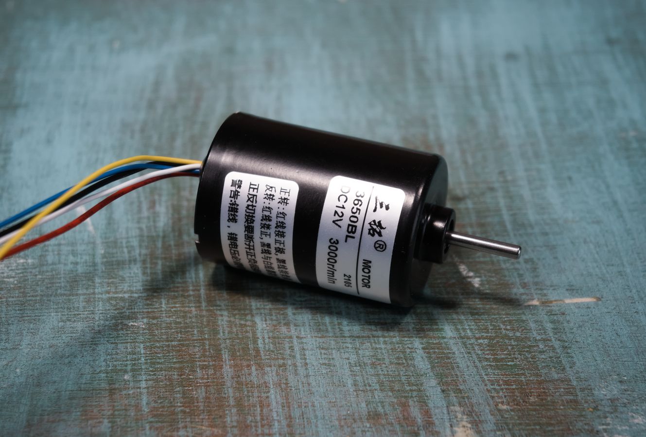
There wasn't much choice in motors that run at a suitably low speed. I found a fairly nice one on eBay with a built-in controller, which makes it easy to control the speed using PWM. The maximum speed of 3000rpm and power of about 15W is a bit high, but useable. Unlike a lot of cheaper motors I looked at, this one had proper specifications, including torque-speed curves, so I could be sure how well it would work before buying it.
I considered a variety of possible ways of enclosing the fan to prevent inadvertent loss of digits. From my experience with PC cooling, I know that the circular metal wire style grilles are particularly good, having a large percentage open area to not restrict airflow, and being mostly parallel to the direction of motion of the fan blades, which means they are quieter than other styles.
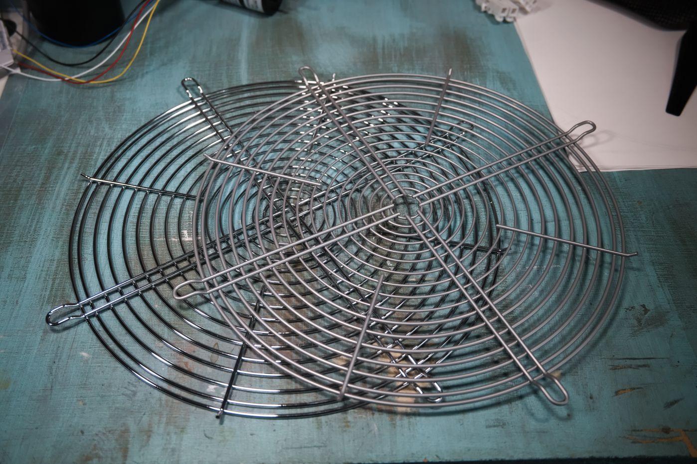
Apparently the size of the fan is at the upper end of what's available in wire grilles, as I had to look quite hard to find any, and without spending too much money could only obtain two that were slightly different (one matte, one polished). It's also not ideal that they have four arms - the same as the number of blades on the fan - as this means all the fan blades pass all the arms of the grilles at the same time, concentrating all the noise emitted into a single frequency. This is more audible than if the noise was spread out over multiple frequencies.
I trimmed a few bits off one of the grilles to leave the innermost ring clear. This happens to be a good fit for the motor, so I didn't have to fabricate any sort of separate mount for it.
Tachometer
As the motor has a tachometer output and I planned to make the fan's speed continuously variable, I thought it would be fun to display its reported speed with an old-school moving-coil panel meter. I couldn't find any off-the-shelf meters with a suitable scale in RPM, so instead I purchased one that had a scale that could be replaced (at least it looked like I could replace it; few meters explicitly specify that the scale is replaceable).
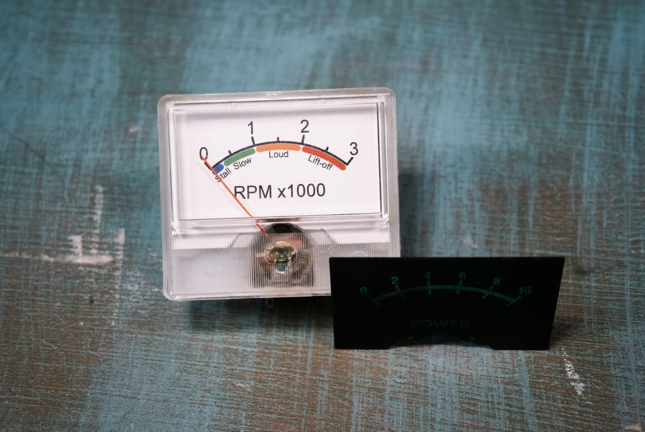
I made a new scale with a maximum of 3000rpm to match the unloaded speed of the motor (with the fan attached it peaks at about 2600rpm). That isn't a very intuitive scale though, so I added a second one underneath with more descriptive labels. I designed the scale using QCAD so I could draw it the right size in mm and then print it out 1:1 on a normal laser printer.
On testing the meter I discovered that it's rather non-linear. Although the meter is really just for decoration and so doesn't need to be accurate, I still wanted it to be accurate. So I took some measurements of input voltage vs. displayed value (from 0-10 on the original scale), then plotted them in Veusz so I could see what shape the curve was, and how to correct it.

Plotted in reverse, i.e. displayed value vs. voltage, the line of best fit is then the function that would have to be applied to the input voltage to make the output linear. It turned out to be roughly a cubic polynomial. This makes sense as moving-coil meters work by having a coil of wire and a magnet, similar to an electric motor. The coil starts off not quite aligned with the magnet, so applying a little voltage to the meter only generates a small force on the needle. Once it's moved a bit it lines up with the magnet so increasing the voltage generates a larger force. Then it moves around the other side of the magnet and goes back to not generating much force. If you're wondering why the axes for the correction curve are labelled "PWM", that will become clear later...
Control
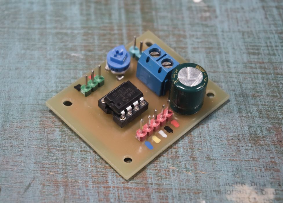
The motor requires a PWM input for speed control, and provides an FM output for the tachometer (not FM radio, but pulses with a frequency proportional to the motor's speed). I needed a way to interface those with a potentiometer and the moving-coil meter respectively. Although possible using basic analogue components, using a microcontroller is much easier, so that's what I did.

I used a PIC12F1571 because it has all the peripherals necessary (an ADC to read the potentiometer, a PWM output to control the motor, and a timer with external trigger to measure the motor's speed), and I happened to have one already.

Here's the firmware. Just the main file is reproduced on this page. If you want to look at the rest, download the zip (most of the rest is just setup code auto-generated by MPLAB Code Configurator, and isn't needed just to understand how it all works).
It doesn't do much. It sets the motor speed according to potentiometer position, and sets the voltage for the panel meter according to motor speed. At this point you can see why the chart of the panel meter's response had axes with PWM values up to 255 - the output from the µC to the meter is PWM with values from 0-255. This is then low-pass filtered to get a DC voltage to power the meter.
The specifications for the motor say the PWM input should be 10-30kHz. However I found that it was a bit quieter at low speeds if the frequency was much higher, so I used 62.5kHz.
Frame
Although I still don't own a 3D printer, I have gained some experience with designing 3D printed parts recently, so I put that experience to use here, using OpenSCAD as I have before.
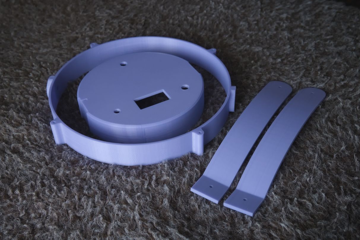
The frame consists of three main parts: The duct, which the fan itself sits inside, and to which the grilles are directly attached; The base allowing the fan to stand on a desk and containing the electronics; A pair of arms connecting the duct to the base, and allowing the duct to pitch up and down.

Where the frame parts need to be connected together I added hexagonal holes in one part to hold nuts, with a bolt to be inserted through the other part. For other fixings that don't need much strength, like attaching the grilles, I just used plain holes that I could tap and then screw into directly.
Having been pleased with Lancashire3D before, I had them print this in purple PLA, to match the room where it will be used. I had it printed at the lowest resolution possible because I actually want it to look 3D printed. It came out quite nicely.
Assembly
Everything fit together as expected. Due to thermal expansion/contraction during printing, small holes can end up smaller than their nominal size. That was the case here, so I had to run them through with a drill. Fortunately the hexagonal holes for insetting nuts were exactly the right size; they would be difficult to adjust after printing.
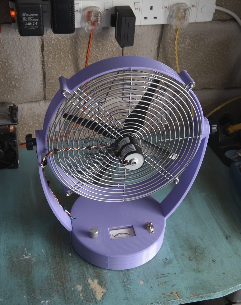
The fan blows backwards compared to normal desk fans - out the side that the motor is mounted. While I could have flipped the propeller over and reversed the motor direction to reverse the airflow, I thought it appropriate to leave it like this because it's made with a drone propeller and this is the way propellers on drones normally work.
The pivots are held together with large thumbscrews/knobs so they can be loosened by hand for adjustment. There's nothing limiting the range of motion except the cable, so it would be possible to cause damage with only a little excess force. If I had thought of it before, I would have added some interlocking parts in the pivot to prevent that. This would only be a problem for a ham-fisted user though.

I used a sheet of transparent plastic to cover underneath the base because it's the only sheet material I had available. It's also nice to be able to see inside without opening it up.
Testing
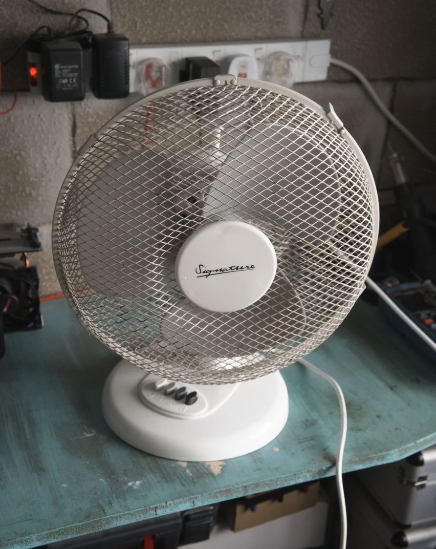
But is it any good? I don't currently have access to the noisy fan that this is intended to replace, so instead I compared it to a "Signature SF12" which is a generic, cheap but reasonably quiet fan. To make the comparison fair, I measured noise and airflow at each of the three speed settings that the SF12 fan offers, then adjusted the speed of my fan to match the three levels of airflow that the SF12 produced.
I don't have anything for measuring airflow, so I crafted a suitable instrument by taping a protractor to a bit of wood, hammering a nail to its centre, then draping a length of paper over the nail. Air moving past the paper pushes it around the nail, with higher airflow causing a higher angle of deflection. It won't give me absolute airflow numbers, but it's good enough for relative measurements.
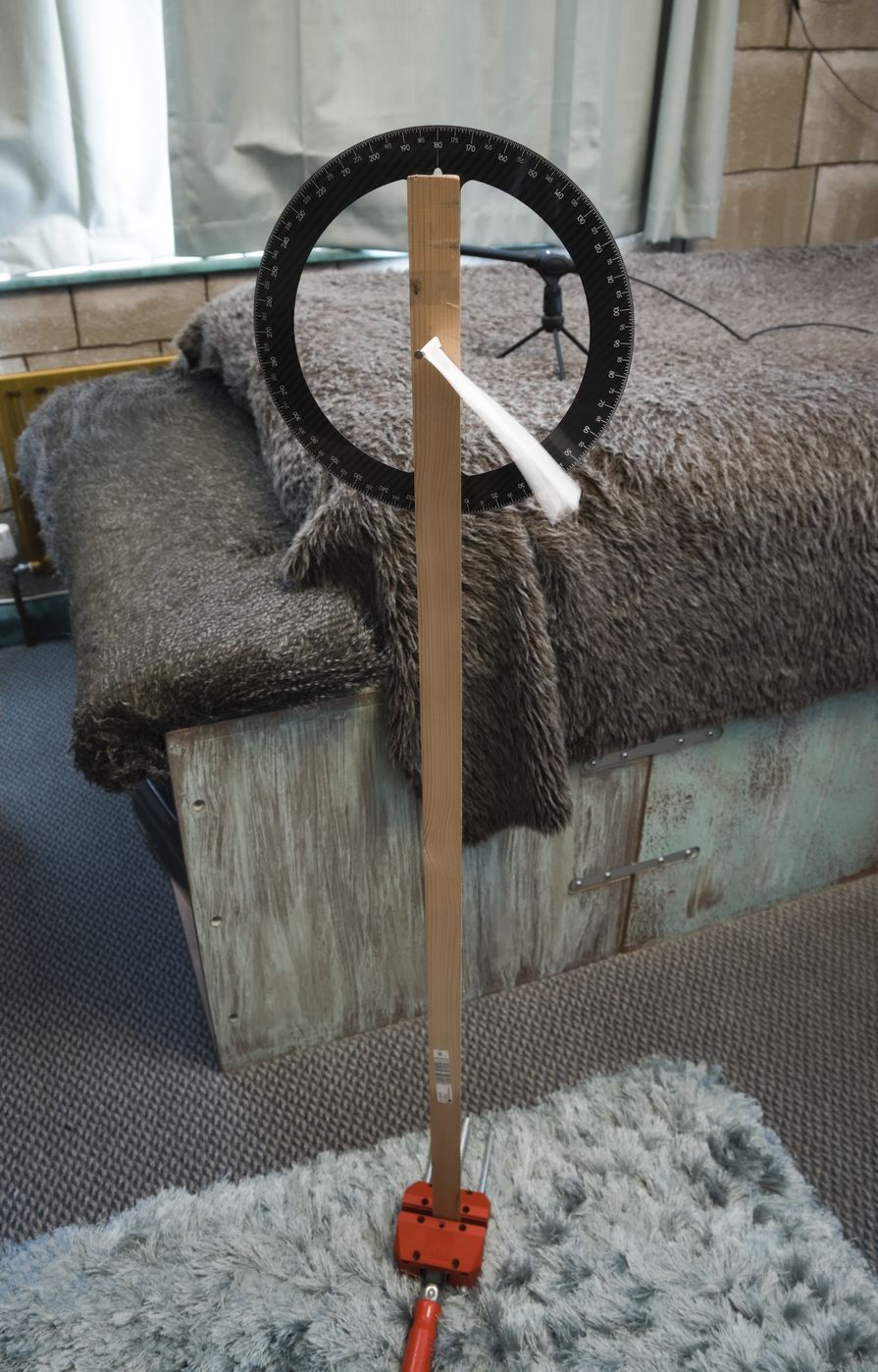
It proved to be quite hard to take a reading from the airflow meter because of turbulence. The reference fan especially produces a non-constant airflow, giving wildly fluctuating readings. I tried to take an average in my head, which is not going to be very accurate, so these measurements are likely to be wrong by quite a lot.
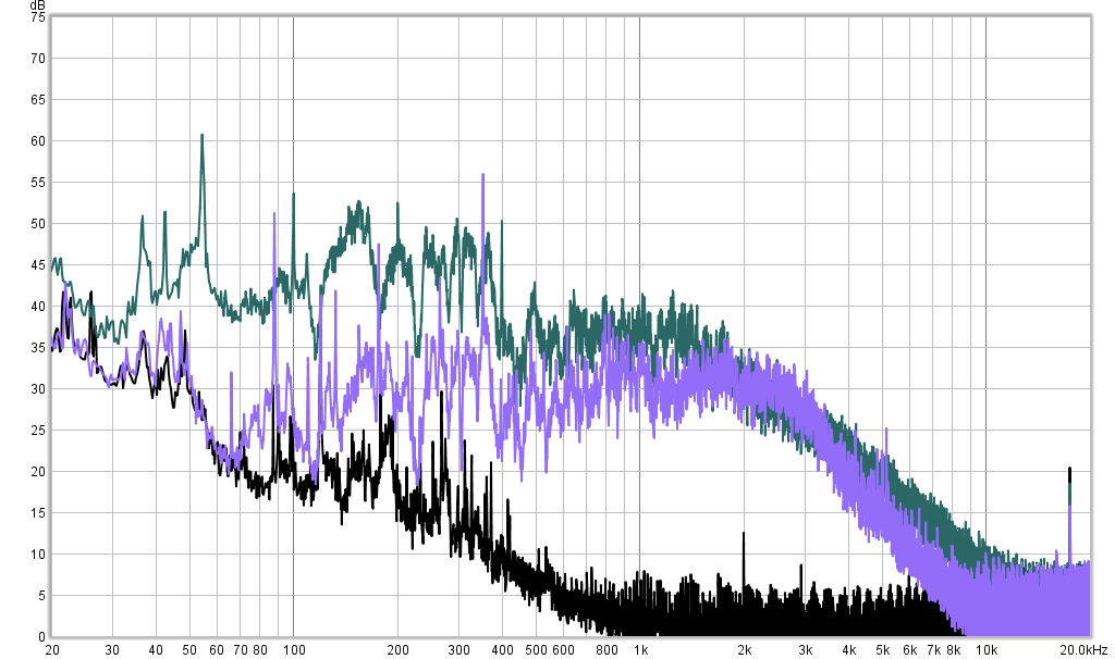
Rather than measuring noise as a single dBA level, I performed a spectrum analysis to show which frequencies were produced. Here are comparisons of the two fans at equal measured airflow. For all FFTs, black is the noise floor, purple is my fan, and green is the reference fan.
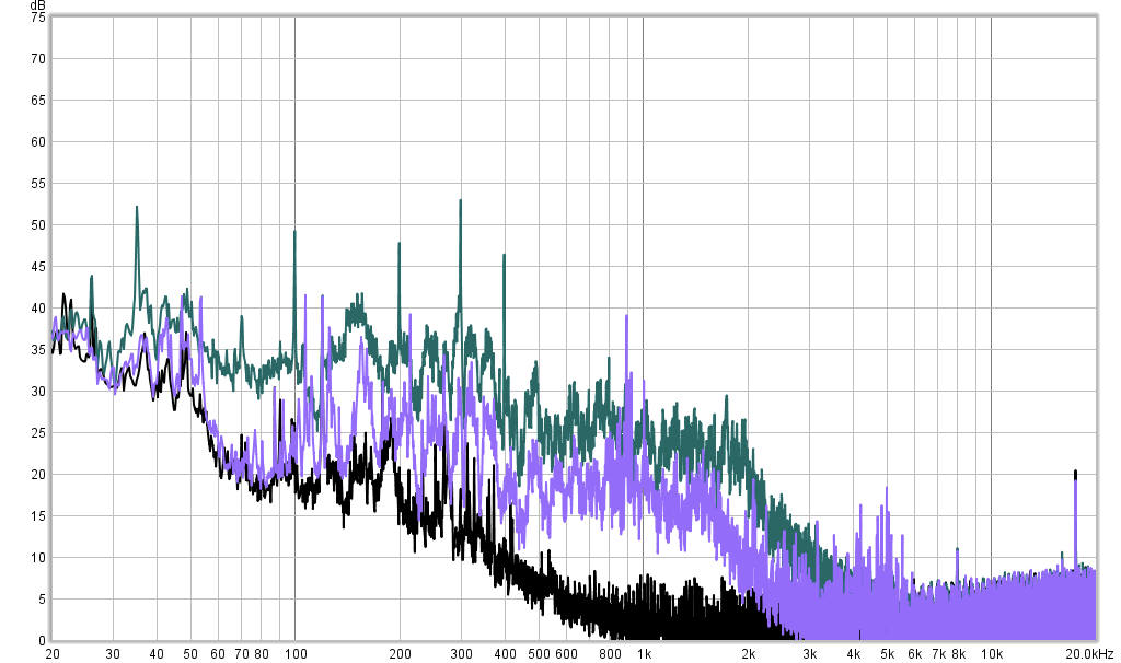
My fan is visibly better here, with the notable exception of a peak at 900Hz, and some smaller peaks at 4-5kHz. Those peaks all seem to be noise from the motor itself. From the other peaks lower down, it's possible to work out that the ref. fan is spinning at about 700rpm, and my fan at about 800rpm.
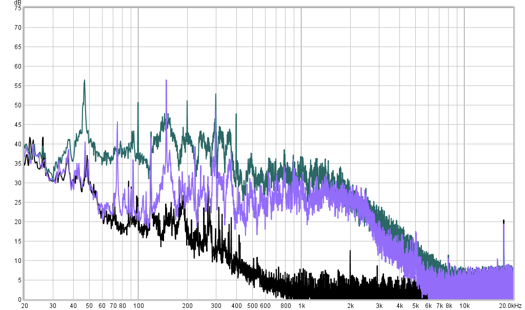
Lower noise overall again, but now there are prominent peaks lower down emitted by my fan, with the one at 150Hz as high as the highest peak from the ref. fan. Speeds this time are about 940rpm for the ref. fan, and 1100rpm for mine.
At the highest speed setting it's similar to before. The ref. fan produces more noise overall, but the noise produced by my fan is more concentrated at specific frequencies. This is audible as a slight humming compared to the almost white noise from the ref. fan. Speeds are 1010rpm for the ref. fan and 1300rpm for mine.
I'm a little surprised that my fan is so much quieter. The ref. fan is probably noisier due to the same turbulence that made it difficult to measure airflow. That might be caused by the fan blades, or the mesh grille, or maybe the large size of the motor (probably an AC induction motor, made bulkier by the automatic yaw mechanism and plastic cover)
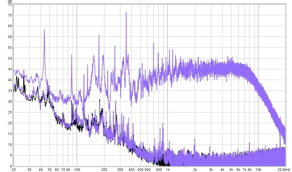
The last FFT shows my fan set to both its highest (2600rpm) and lowest (230rpm) speeds. At the lowest speed it's not much higher than the noise floor except some peaks produced by the motor, with airflow that can barely be felt. At the highest speed it's pretty loud, and also pushes a lot of air.
I didn't attempt to measure vibration, but a basic test of putting my hand on top of each fan revealed that the ref. fan vibrates quite a bit, though not enough to cause the desk it was standing on to emit sound like some really bad fans do. My fan only vibrates a little.
I'm pleased with the result. Although the peaky noise is more objectionable than the more white noise from the ref. fan at the same volume, the lower overall volume makes up for it. The measurements correspond to what I was expecting given the non-ideal four-bladed propeller. Maybe if I had managed to obtain a three or five-bladed one it would have been even better. The fan could also have been improved by a quieter motor, but I don't know where to obtain one.